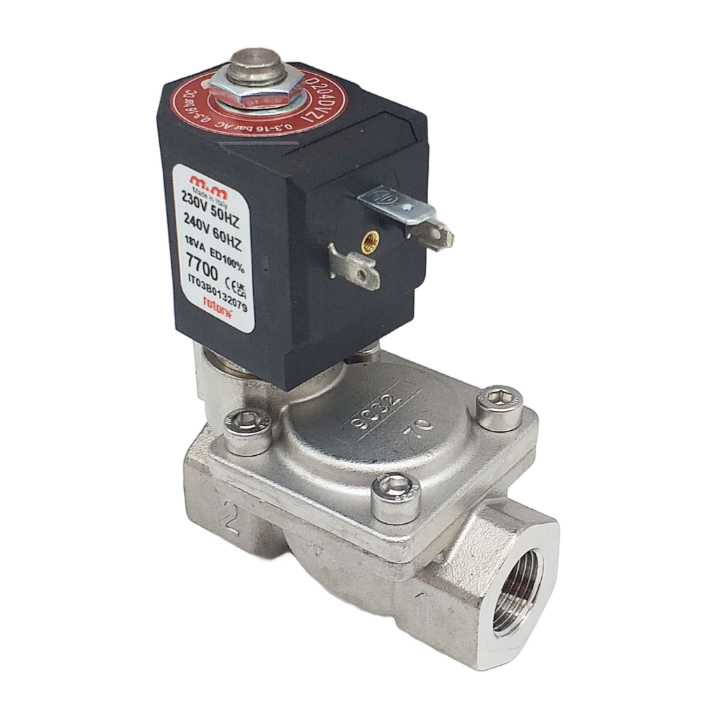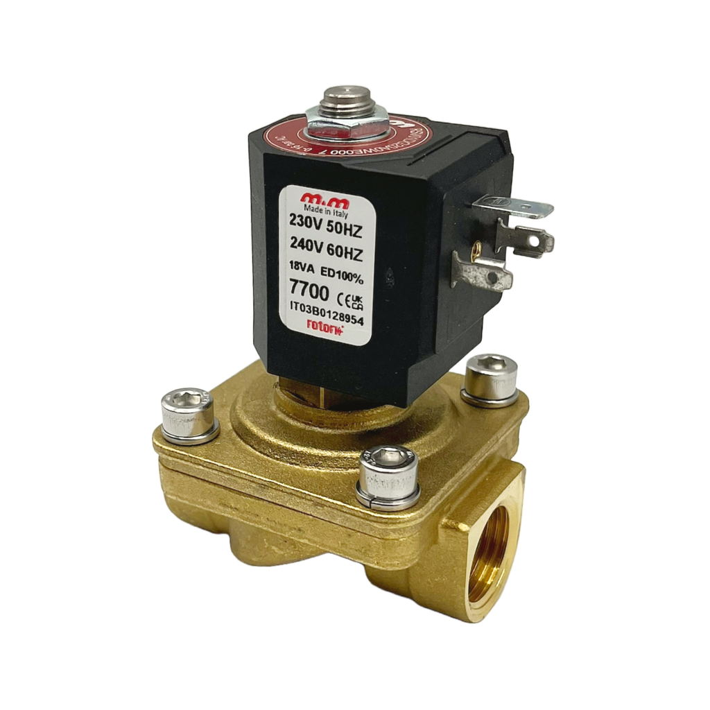
Solenoid Valves – Installation, Maintenance and Problem Solving


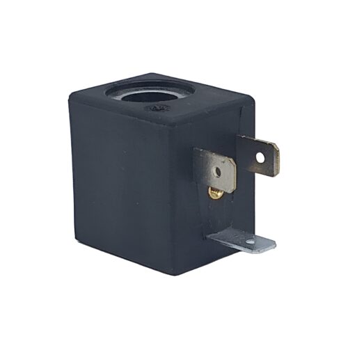
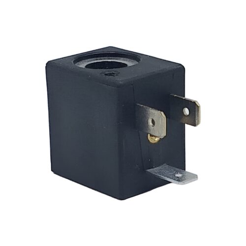
Spare Coils
-
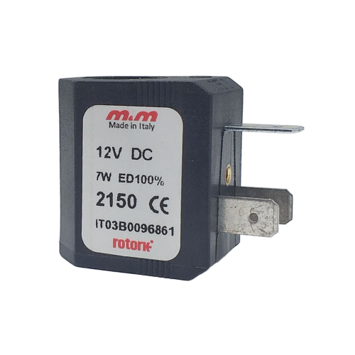
2150
 From £24.44
Select optionsView Product
From £24.44
Select optionsView Product -
2100
From £24.44
Select optionsView Product -
2200
From £24.24
Select optionsView Product -
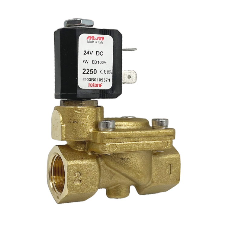
2250
From £24.24
Select optionsView Product -
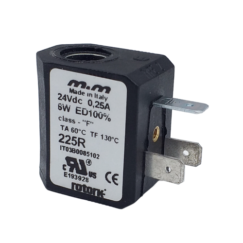
225R
From £30.65
Select optionsView Product -
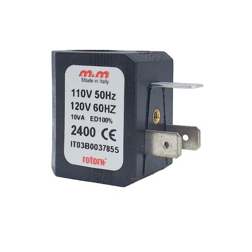
2400
From £24.24
Select optionsView Product -
2700
From £24.24
Select optionsView Product -
270R
From £30.65
Select optionsView Product -
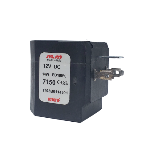
7150
From £34.59
Select optionsView Product -
7151
From £53.13
Select optionsView Product -
71Z1
From £60.25
Select optionsView Product -
7200
From £32.70
Select optionsView Product -
7201
From £50.20
Select optionsView Product -
72K1
From £52.72
Select optionsView Product -
7250
From £32.70
Select optionsView Product -
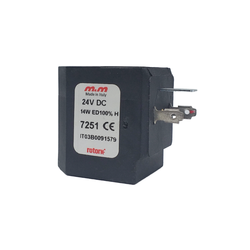
7251
From £50.20
Select optionsView Product -
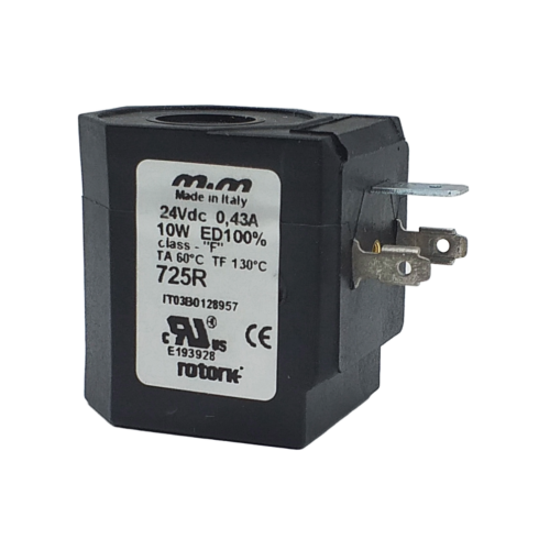
725R
From £42.16
Select optionsView Product -
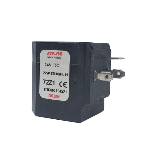
72Z1
From £60.25
Select optionsView Product -
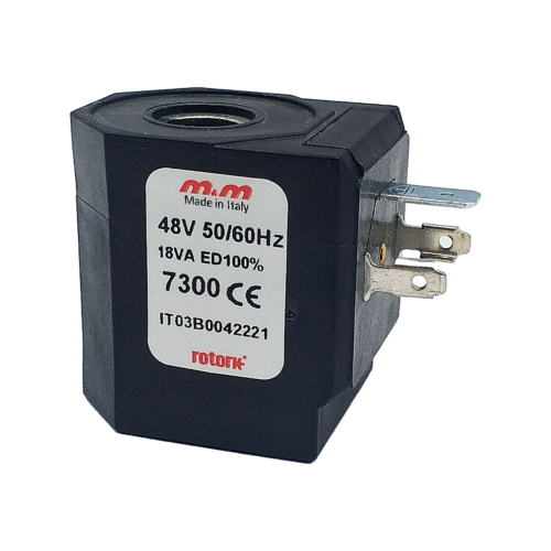
7300
From £34.58
Select optionsView Product -
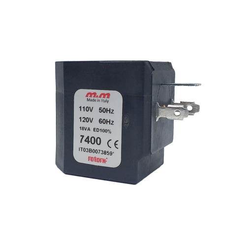
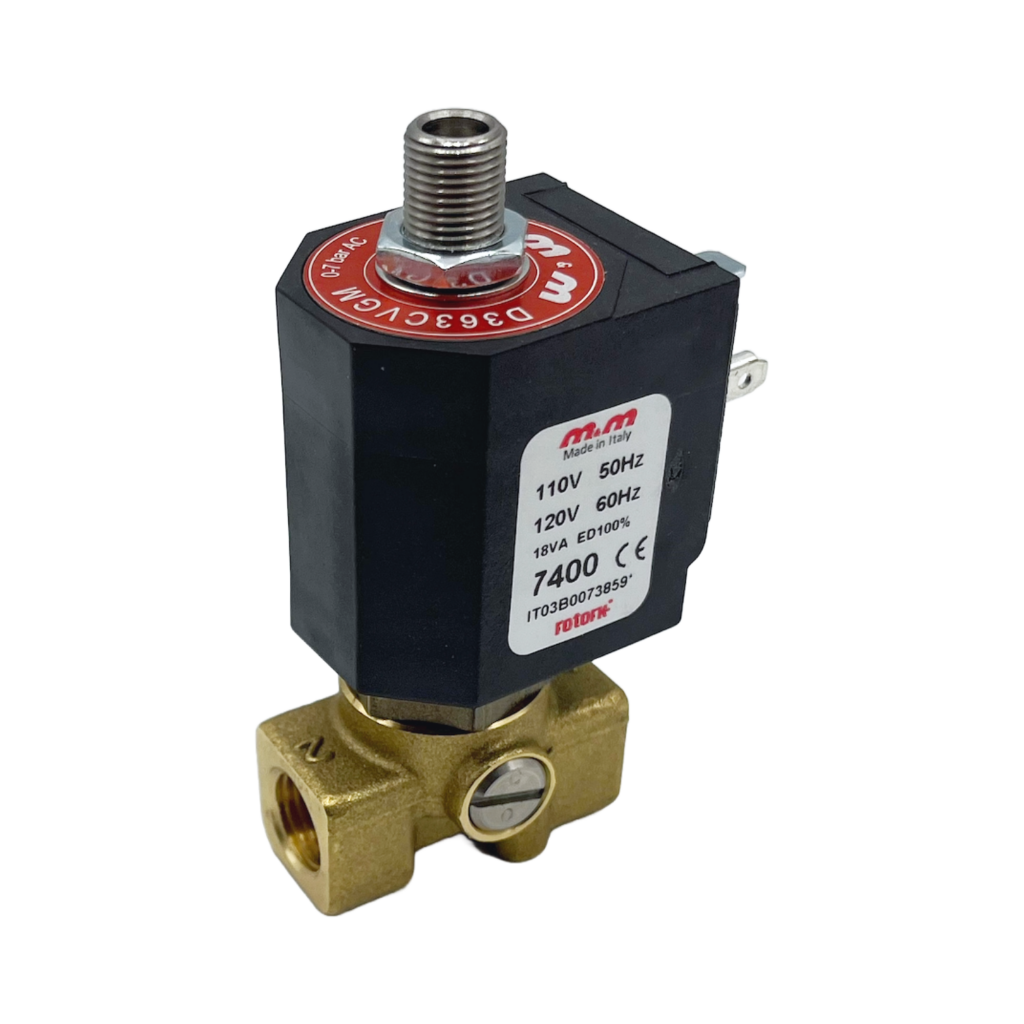
7400
From £32.70
Select optionsView Product -
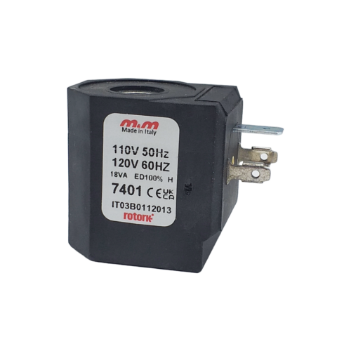
7401
From £50.20
Select optionsView Product -
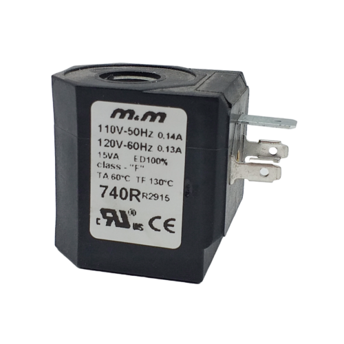
740R
From £42.16
Select optionsView Product -
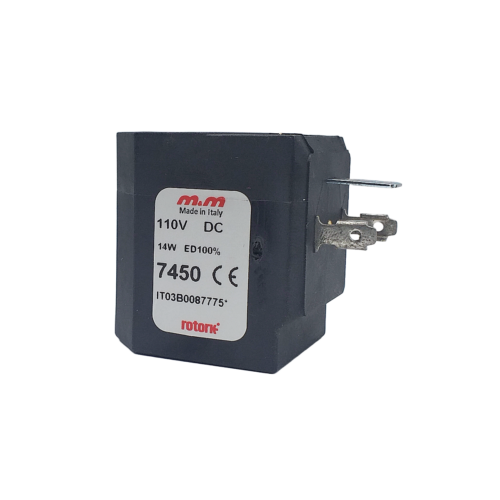
7450
From £32.69
Select optionsView Product -
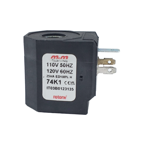
74K1
From £50.20
Select optionsView Product -
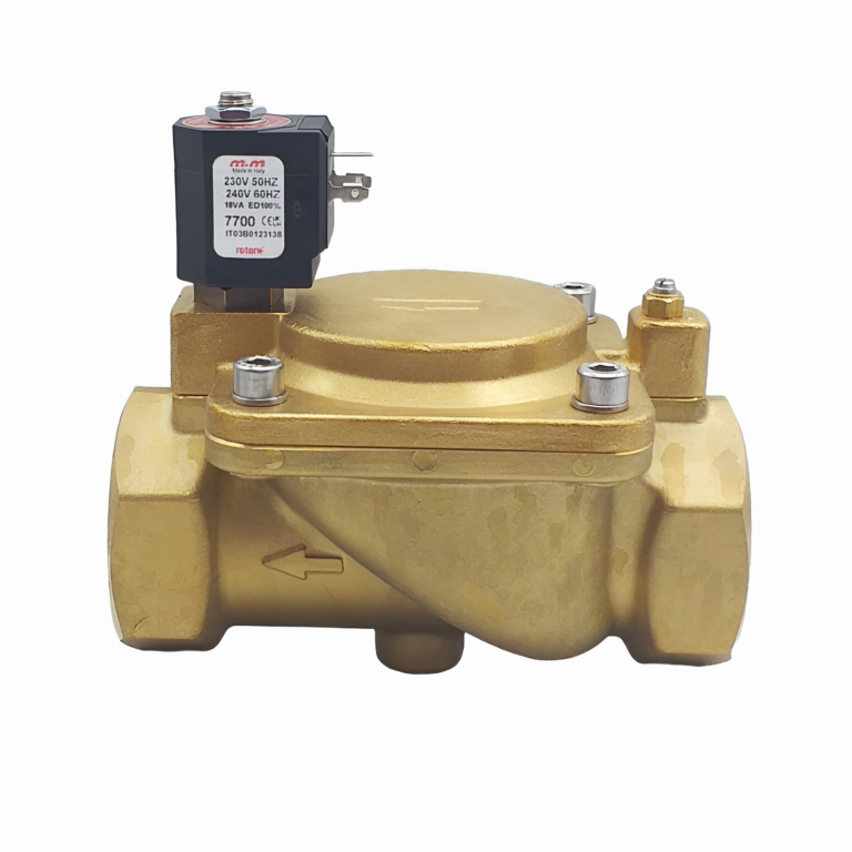
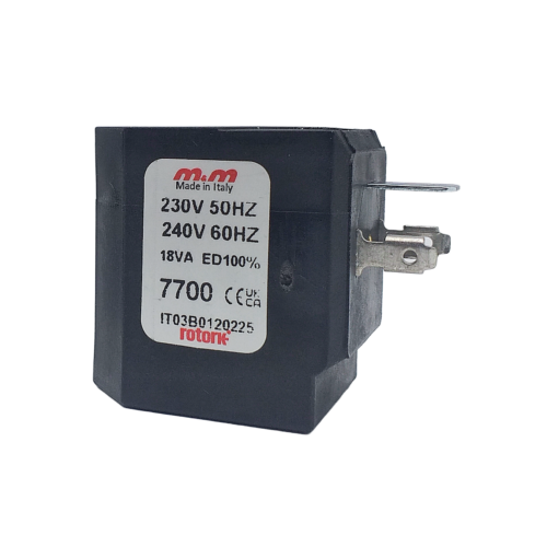
7700
From £32.70
Select optionsView Product -
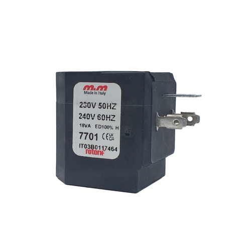
7701
From £50.20
Select optionsView Product -
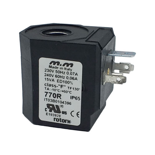
770R
From £42.16
Select optionsView Product -
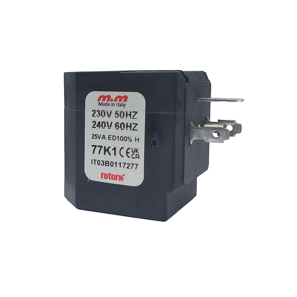
77K1
From £52.72
Select optionsView Product -
R2G 2801
From £15.09
Select optionsView Product -
R2G 280D
From £15.09
Read moreView Product -
R2G 280E
From £15.09
Select optionsView Product -
R2G 3601
From £27.81
Select optionsView Product -
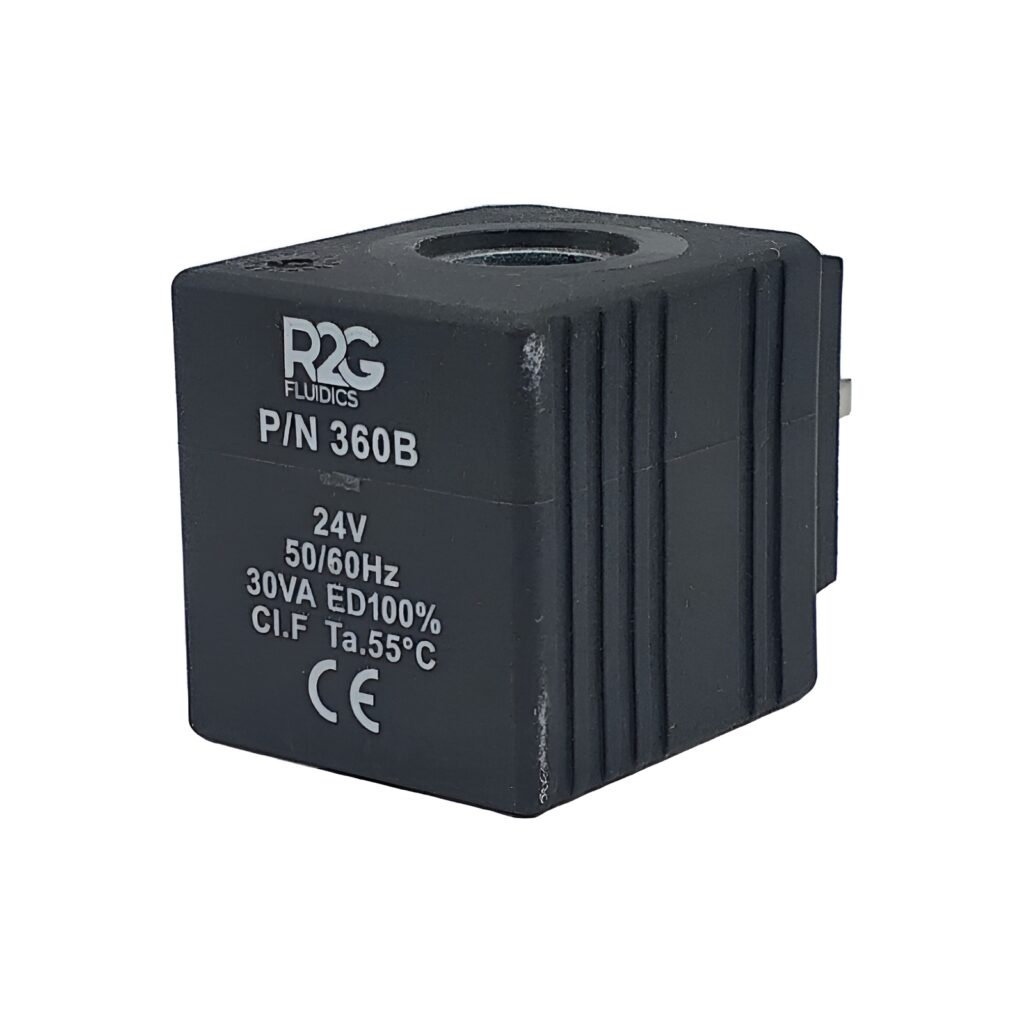
R2G 360B
From £27.81
Select optionsView Product -
R2G 360E
From £27.81
Select optionsView Product